ESXI PowerShell command to Automate ESXI configuration

 # Prompt for vCenter password

$VCCred = Get-Credential

$vCenter = Read-Host "Enter vCenterName"


#$targetVC = 192.168.1.20


#Connect vCenter 

#Connect-VIServer -Server $vCenter -Credential $VCCred


$DataCenter1= Read-Host "Enter Datacenter host"


#$datacenter = Get-Datacenter "Demo_DC"


#Prompt for ESXI

$ESXI = Read-Host "Enter ESXI hostName" 

$ESXICred= Get-Credential


#Connect ESXI host

Connect-VIServer -Server $ESXI -Credential $ESXICred


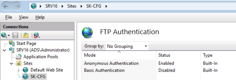
# Add NTP server details

$NTPServer=Read-Host "Write NTP server details"

#Add-VmHostNtpServer -VMHost $esxi -NtpServer servername

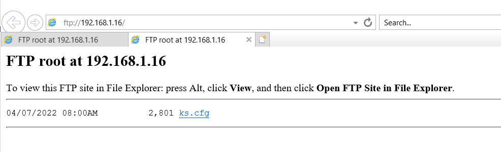
#Add-VMHostNtpServer -VMHost $esxi -NtpServer 192.168.1.16


Add-VMHostNtpServer -VMHost $ESXI -NtpServer $NTPServer

# Create Datastore

$DataStore= Read-Host "Volume Name"

#Storage Device path


$DevicePath= Read-Host "Enter Storage device path"


#New-Datastore -VMHost $ESXI -Name $DataStore -Path mpx.vmhba0:C0:T1:L0 -VMFS -FileSystemVersion 6

New-Datastore -VMHost $ESXI -Name $DataStore -Path $DevicePath -Vmfs -FileSystemVersion 6


# To update Domain name, prefered DNS and SearchDomain


$vmHostNetworkInfo = Get-VmHostNetwork -Host $ESXI


Set-VmHostNetwork -Network $vmHostNetworkInfo -VMKernelGateway 192.168.1.1 -DomainName ads.com -SearchDomain ads.com -DnsAddress 192.168.1.16 -DnsFromDhcp $false


#Add host to vCenter

Add-VMHost -Server $targetVC -Name $ESXI -Location $DataCenter1 -Credential $ESXICred -Force


#Enable Storage IO Control


Set-Datastore -Datastore $DataStore -StorageIOControlEnabled $true

Set default homepage and startup page in Chrome and Microsoft Edge | Windows 10 Workgroup Machine

 Set default homepage and startup page of Chrome and Microsoft Edge in windows 10 workgroup machine


If you want to set the homepage and startup page in Windows10 that is part of domain member then it is possible but if you want to apply same thing in workgroup machine then it won’t work.


To apply the homepage and startup page in Google chrome you can use an alternate method. Once you set the homepage and startup page using this method it will apply to all local users and all local users will be able to open the same homepage.


C:\ProgramData\Microsoft\Windows\Start Menu\Programs

Right click on Google Chrome -> Properties 

Shortcut -> Target -> Enter homepage URL name at the end of file path “ ………………………………


Apply and Ok

Do the same with Microsoft Edge and apply Okay


Remove existing shortcut from desktop and taskbar and


Use below link to apply same window tiles and taskbar for all users 

or create new shortcut from start menu

http://www.mytechinfoit.com/2022/04/steps-to-customize-windows-start-layout.html 


Cisco UCS Dynamic Pinning Overview

 Cisco UCS Dynamic Pinning Overview


Dynamic Pinning

This is the default pin group setting. In dynamic pinning, Fabric Interconnect automatically binds server vNICs to uplink FI ports. The mapping of server vNICs to uplink FI ports depends upon the total number of active uplinks configured, which could be either 1, 2, 4, or 8 (for older 6100 series FIs, uplinks could only be 1, 2, and 4).


Failure Response in Dynamic Pinning

Both Fabric Interconnects are in Active/Active mode with respect to Ethernet data traffic movement. Each server is pinned to a single Fabric Interconnect uplink port or port channel. This means that the data traffic from some servers will move using Fabric Interconnect A and for other servers using Fabric Interconnect B.


In case of a northbound uplink or port channel failure where a server is currently pinned to, the server connection will be automatically pinned to another port or port channel on the same Fabric Interconnect. In case of a complete Fabric Interconnect failure, the server will be automatically pinned to any uplink port or port channel on the second Fabric Interconnect provided that the Fabric failover is configured for the vNIC. The Fabric Interconnect will update the northbound switch about this change using Gratuitous Address Resolution Protocol (GARP).


The dynamically pinned server vNIC uplinks are automatically rebalanced after 300 seconds to distribute the data traffic load on both Fabric Interconnects.


No user configuration is required for dynamic pinning. If no static pin groups are configured, dynamic pinning will be automatically used. Dynamic pinning is the recommended configuration and static pinning should only be used for business use cases.


Login to UCS manager

From left side select LAN


Go under the Policies -> select vNIC Templates


Right click vNIC Templates and select create vNIC template


Name-: Type template name

Select enable failover

Redundancy -: Select as per your requirement

Click Okay


What is Cisco Intersight? Steps to connect Cisco Intersight with USC Manager/ HyperFlex

 What is CISCO Intersight?

Cisco Internight is a cloud operations platform that consists of optional, modular capabilities of advanced infrastructure, workload optimization, and Kubernetes services. Cisco Intersight infrastructure services include the deployment, monitoring, management, and support of your physical and virtual infrastructure.


How to connect CISCO internight with USC Manager/ HyperFlex 

Go to internet browser

Open below link

https://www.intersight.com/


Login with Cisco id or SSO 


If you are login first time then you will receive below message


Click create an account


Accept the license


Enter Account Name (A-Z 0-9)


This is welcome page


Click Admin


Click Claim a new target


Now login to UCS manager console


Select Admin and from drop down select Device connector


Click turn on to generate Device id and claim code


Now go to Cisco intersight

Click Admin -> claim a new target


Select the application that you want to connect from list

Click start

Enter device ID and claim code


Click claim


CISCO UCS Fabric interconnect port configure as server, uplink, FCoE, FCoE storage port in CISCO UCS

How to configure Fabric interconnect port as server, uplink, FCoE, FCoE storage port in CISCO UCS


Fabric Interconnects

The Fabric Interconnect (FI) is the core component of a UCS solution, providing network, storage, and unified management capabilities to servers.


Fabric Interconnects are typically configured as highly available cluster pairs in production environments and provide active-active data traffic.


 A single FI-based design is also possible for proof of concept (POC) but not recommended for a production environment.


Steps to configure FI port as server port 

Login to UCS manager

Click Equipment from left list

In box just right to equipment drop down and select Fabric interconnect


Right click on any of the free port and select configure as server port


Or you can select multiple ports and configure as server port


Expend Fabric interconnect -> Ethernet ports

Select multiple ports 


Right click on selected port and select configure as server port


Click Yes


Now ports have configured as server port


Now select equipment and drop down

From drop down list click Chassis

Select the chassis for whom that you want to check connectivity

Click hybrid display


Similarly you can select multiple ports and can configure as FCoE “Fiber channel over Ethernet”


Main topology view


Script for unattended esxi installation using ftp server | KickStart script


You can use scripts for unattended ESXi installation or upgrade, scripted installations or upgrades provide an efficient way to deploy multiple hosts.


The installation or upgrade script contains the installation settings for ESXi. You can apply the script to all hosts that you want to have a similar configuration.


For a scripted installation or upgrade, you must use the supported commands to create a script. You can edit the script to change settings that are unique for each host.


The installation or upgrade script can reside in one of the following locations:


FTP server

HTTP/HTTPS server

NFS server

USB flash drive

CD-ROM drive

In my lab I am keeping the installation script in FTP and HTTP server.


You can download the script from below link and save the script win KS.CFG

http://www.mytechinfoit.com/2022/04/script-to-automate-esxi-deployment.html 


Steps to configure FTP server.


Login to server

Go to server manager

Add Roles and features -> Follow the screen

Check web server IIS

FTP server

Select FTP service


Click next and follow the screen and install

Once installation complete

Open IIS manager


Right click on site and click Add  FTP site


Give the FTP site name

In content directory give the physical location of script file

I have kept script file in c:\esxi folder


Click next 

Select IP address to bind the address, in my Lab setup I am using single IP, if there is multiple assigned on the server then it will show in list


Select No SSL


In Authentication type

Select Anonymous

And anonymous users


In permission 

Select Read


Then click finish

Now select newly created FTP site SK-CFG

Click FTP authentication and enable Anonymous authentication if it is not already enabled

Once you enable it then anyone can access this FTP content without login.


Also click on FTP authorization rule to recheck whether anonymous users are allowed or not


Now go to the client machine and check whether FTP is working or not.

Open browser and enter FTP path-> ftp://192.168.1.16/ 


Now FTP page is opening without entering any user ID or password


Steps to install unattended ESXI 


If you are using physical server for deployment, then mount ESXI ISO and boot the server using CD/DVD

And follow below steps, in my case I am deploying ESXi in VMware workstation.

Steps will be the same for both Physical and Virtual only, the booting process will be different.


For a physical server you need to launch iLO console and mount ISO and boot from there.

In the VMware workstation we need to edit the VM setting and assign the ISO path and boot the server.


Once you will boot the server using ISO at first boot press SHIFT=O to edit boot options 


Now enter FTP address one temp IP to communicate with the FTP server like below.


Press enter.

Now installation has started


Post installation server will auto reboot and do the entire configuration that has been updated in the script.

Finally installation completed with the same configuration that had updated in script file.


Thank you!!!!


Script to automate ESXI deployment

 ################################################

## vSphere ESXi 7.0 Scripted Install - Part 1 ##

################################################

# Accept the VMware End User License Agreement

vmaccepteula


# Set the root password for DCUI

rootpw Passw0rd!!


# Install on the first local disk available on machine

install --firstdisk --overwritevmfs


# Set the network to Static on the first network adapter

network --hostname=esxi7-Auto --device=vmnic0 --bootproto=static --ip=192.168.1.215 --netmask=255.255.255.0 --gateway=192.168.1.1 --nameserver=192.168.1.16


# Reboot

reboot


################################################

## vSphere ESXi 7.0 Scripted Install - Part 2 ##

################################################


# Use busybox interpreter

%firstboot --interpreter=busybox


# Set DNS Suffix

esxcli network ip dns search add --domain=ads.com


# Disable IPv6

esxcli network ip set --ipv6-enabled=false


# Enable SSH

vim-cmd hostsvc/enable_ssh

vim-cmd hostsvc/start_ssh


# Enable NTP

echo "server 0.au.pool.ntp.org" >> /etc/ntp.conf;

echo "server 1.au.pool.ntp.org" >> /etc/ntp.conf;

/sbin/chkconfig ntpd on;


# Create vSwitches

esxcli network vswitch standard add -v vSwitch1

esxcli network vswitch standard add -v vSwitch2


# Set vSwitch MTU's

esxcli network vswitch standard set -v vSwitch1 -m 9000

esxcli network vswitch standard set -v vSwitch2 -m 9000


# Add Additional NIC to vSwitches

esxcli network vswitch standard uplink add --uplink-name=vmnic1 --vswitch-name=vSwitch0

esxcli network vswitch standard uplink add --uplink-name=vmnic2 --vswitch-name=vSwitch1

esxcli network vswitch standard uplink add --uplink-name=vmnic3 --vswitch-name=vSwitch1

esxcli network vswitch standard uplink add --uplink-name=vmnic4 --vswitch-name=vSwitch2

esxcli network vswitch standard uplink add --uplink-name=vmnic5 --vswitch-name=vSwitch2


# Create VMKernel Ports

esxcli network vswitch standard portgroup add --portgroup-name=vMotion --vswitch-name=vSwitch1

esxcli network vswitch standard portgroup add --portgroup-name=NFS --vswitch-name=vSwitch2

esxcli network ip netstack add --netstack=vmotion

esxcli network ip interface add --interface-name=vmk1 --portgroup-name=vMotion --netstack=vmotion --mtu=9000

esxcli network ip interface add --interface-name=vmk2 --portgroup-name=NFS --mtu=9000

esxcli network ip interface ipv4 set --interface-name=vmk1 --ipv4=192.168.10.215 --netmask=255.255.255.0 --type=static

esxcli network ip interface ipv4 set --interface-name=vmk2 --ipv4=192.168.5.215 --netmask=255.255.255.0 --type=static


# Put host in maintenance mode

esxcli system maintenanceMode set -e true


# Reboot to apply settings (disabling IPv6)

esxcli system shutdown reboot -d 15 -r "rebooting after disabling IPv6"

Steps to customize windows start layout and taskbar using group policy

 Steps to customize windows start layout and taskbar using group policy


To prepare a Start layout for export, you simply customize the Start layout on a test computer.

To prepare a test computer

Set up a test computer on which to customize the Start layout. Your test computer should have the operating system that is installed on the users’ computers. Install all apps and services that the Start layout should display.


Create a new user account that you will use to customize the Start layout.


To customize Start


Sign in to your test computer with the user account that you created.


Customize the Start layout as you want users to see it by using the following techniques:


Pin apps to Start. From Start, type the name of the app. When the app appears in the search results, right-click the app, and then click Pin to Start.


To view all apps, click All apps in the bottom-left corner of Start. Right-click any app, and pin or unpin it from Start.


Unpin apps that you don’t want to display. To unpin an app, right-click the app, and then click Unpin from Start.


Drag tiles on Start to reorder or group apps.


Resize tiles. To resize tiles, right-click the tile and then click Resize.


Create your own app groups. Drag the apps to an empty area. To name a group, click above the group of tiles and then type the name in the Name group field that appears above the group.


Initial start layout and task manager setting on my test machine “Database


Now you need to pin/unpin from start and taskbar as per your requirements.


Here I have pined application in start menu and taskbar as per my requirement in my test machine “Database


Now launch PowerShell

Run below command to generate start layout .xml file

You can export application path using


AppUserModelID or DesktopApplicationLinkPath 

It depends on the OS where you are running this script.


Export-StartLayout -Path C:\Temp\startlayout010422.xml 


Now go to machine open gpedit.msc


Local Computer Policy -> Computer Configuration ->Administrative Templates -> Start Menu and Taskbar -> 


Double click on Start Layout -> Enable and enter .xml file path


If you want to configure for User only then you need to select User configuration -> Administrative Templates -> Start Menu and Taskbar -> 


Double click on Start Layout  -> Enable and enter .xml file path


Run Gpupdate /force and restart the machine and try with any local user.

Once this policy is implemented, users can’t customize the Start layout.


To configure taskbar in windows you need to do some modification in existing .xml file


Add xmlns:taskbar="http://schemas.microsoft.com/Start/2014/TaskbarLayout" to the first line of the file, before the closing >


Like below


Use below layout setting between 

</DefaultLayoutOverride>


</LayoutModificationTemplate>

And add DesktopApplicationLinkPath with application name .ink in between like below


<CustomTaskbarLayoutCollection>

      <defaultlayout:TaskbarLayout>

        <taskbar:TaskbarPinList>

          <taskbar:UWA AppUserModelID="Microsoft.MicrosoftEdge_8wekyb3d8bbwe!MicrosoftEdge" />

          <taskbar:DesktopApp DesktopApplicationLinkPath="%APPDATA%\Microsoft\Windows\Start Menu\Programs\System Tools\File Explorer.lnk" />

        </taskbar:TaskbarPinList>

      </defaultlayout:TaskbarLayout>

    </CustomTaskbarLayoutCollection>


Save the .xml file and again run gpupdate /force and check with any local user.

Now the same taskbar and start layout will apply to all users.


Thanks!!!!


Featured Post

HPE MSA 2040 configuration step by step

HPE MSA 2040 configuration Default IP range for HP SAN storage MSA 2040 is 10.0.0.1/2 You need to connect your laptop and storage with...